Modbus Protocol
/ 4 min read
Updated:Table of Contents
Serial communication
Serial communication transfers data sequentially over one or more signal lines. The term describes a broad transmission method rather than a single protocol. Examples include UART links, CAN, I2C, and serial data carried over RS-232 or RS-485 electrical interfaces.
Protocol stacks and the OSI model
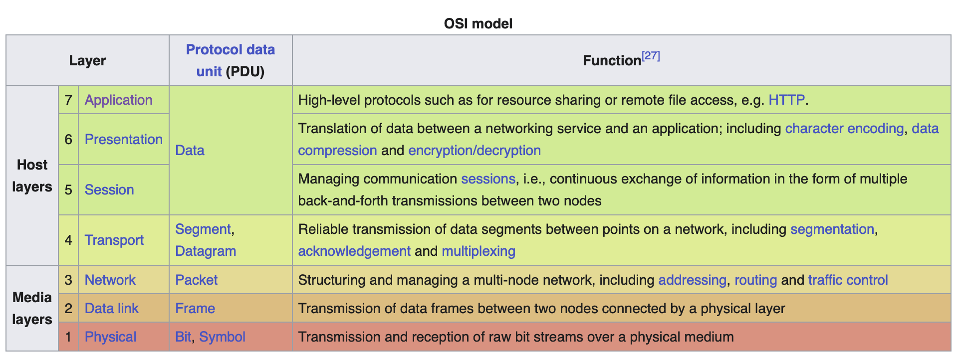
The Open Systems Interconnection model describes seven conceptual layers. A practical embedded protocol does not need to implement a visible counterpart to every layer.
RS-485 and RS-232
RS-485 and RS-232 primarily define electrical characteristics. They do not define Modbus addresses, register meanings, or application messages.
RS-485
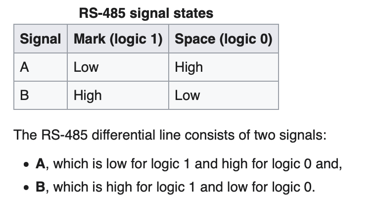
RS-485 uses differential signaling, normally represented by the voltage difference between lines A and B. It must not be reduced to a single-ended fixed “+5 V high” value. A multidrop Modbus network commonly uses two-wire, half-duplex RS-485 with termination at both ends and biasing at one location.
RS-232
RS-232 is a point-to-point, single-ended interface using bipolar voltage ranges. Its signaling voltage is not fixed at ±12 V, and its logical polarity is inverted relative to a typical TTL UART signal. A level shifter is required between most microcontroller UART pins and an RS-232 connector.
UART
A UART implements asynchronous character framing and typically contains:
- a clock generator, usually a multiple of the bit rate to allow sampling in the middle of a bit period
- input and output shift registers, along with the transmit/receive or FIFO buffers
- transmit/receive control
- read/write control logic
Modbus
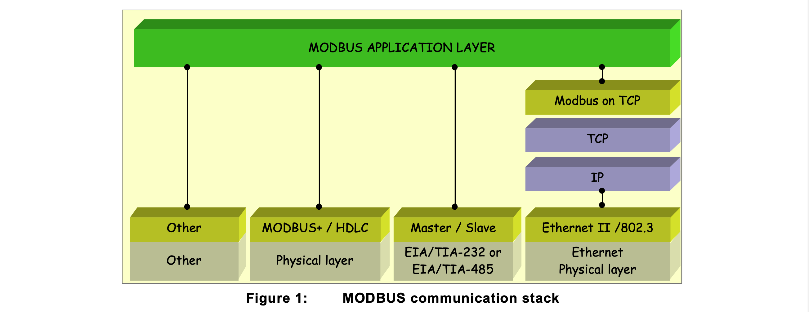
Modbus defines an application protocol. Common variants include Modbus RTU and Modbus ASCII over serial lines, Modbus TCP over TCP/IP, and the legacy proprietary Modbus Plus network. This article focuses on Modbus over Serial Line.
PDU and ADU
The protocol data unit (PDU) is independent of the underlying transport. A transport adds addressing and error-checking fields to form an application data unit (ADU).

Protocol data unit
The PDU consists of a one-byte function code followed by function-specific data and has a maximum length of 253 bytes.

- Function code: 1 byte
- Data: up to 252 bytes; its structure depends on the function
Application data unit
A serial Modbus ADU is address + PDU + error check and is at most 256 bytes. A Modbus TCP ADU uses an MBAP header and is at most 260 bytes.
Modbus serial-line ADU
-
address: 1 byte
-
PDU: function code and data
-
error check: CRC for RTU or LRC for ASCII
-
Server addresses range from 1 through 247.
-
Address 0 is the broadcast address, not the client’s address. Servers do not respond to broadcasts.
-
Modern Modbus terminology uses client/server; older serial documentation often uses master/slave.
Modbus RTU
RTU stands for Remote Terminal Unit. A message must be transmitted as a continuous stream of characters.
The default RTU character format is one start bit, eight data bits sent least-significant bit first, even parity, and one stop bit. Odd parity may also be configured. When no parity is used, two stop bits maintain an 11-bit character frame.

- 1 byte slave address
- 1 byte function code
- 0-252 bytes data
- 2 bytes CRC
- CRC-16/Modbus, transmitted low byte first; polynomial
x^{16}+x^{15}+x^2+1
Frames are separated by at least 3.5 character times. If a gap longer than 1.5 character times occurs inside a frame, the receiver treats the frame as incomplete. Above 19,200 bit/s, the specification recommends fixed values of 750 µs for the inter-character timeout and 1.750 ms for the inter-frame delay.
Modbus ASCII
Modbus ASCII represents each data byte as two hexadecimal ASCII characters. A frame begins with : and ends with CRLF. It contains the address, function, data, and an LRC encoded as ASCII characters.

Transactions
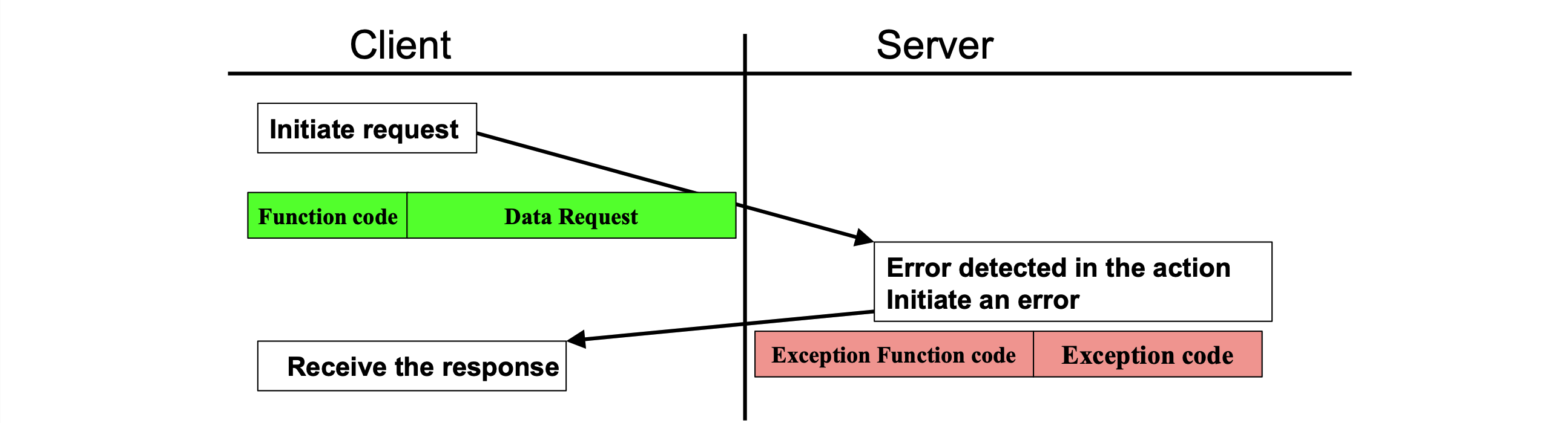
Example
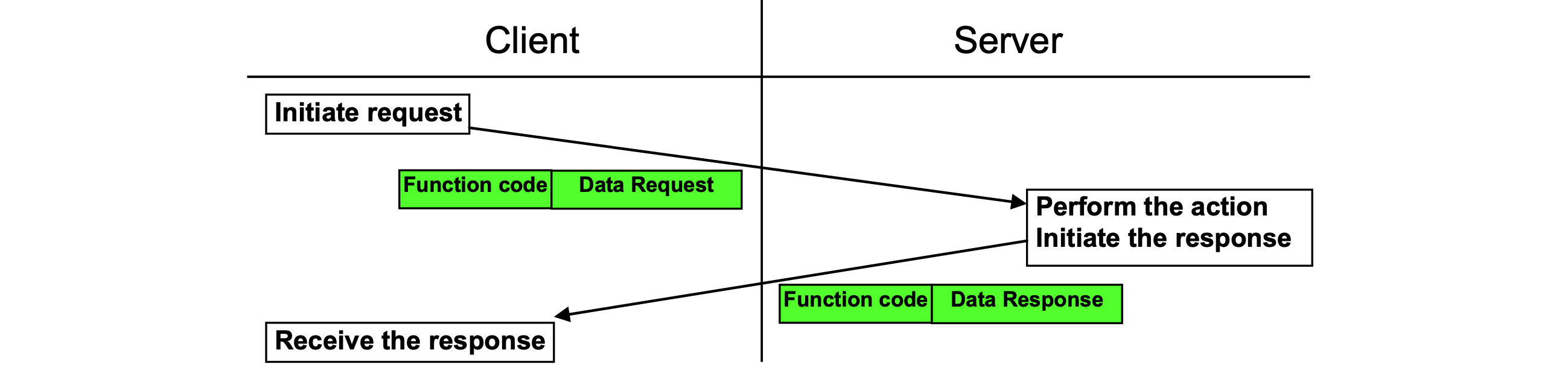
Client to server request: 01 04 00 54 00 0C B0 97
- Address:
01 - PDU:
04 00 54 00 0C- Function code:04, read input registers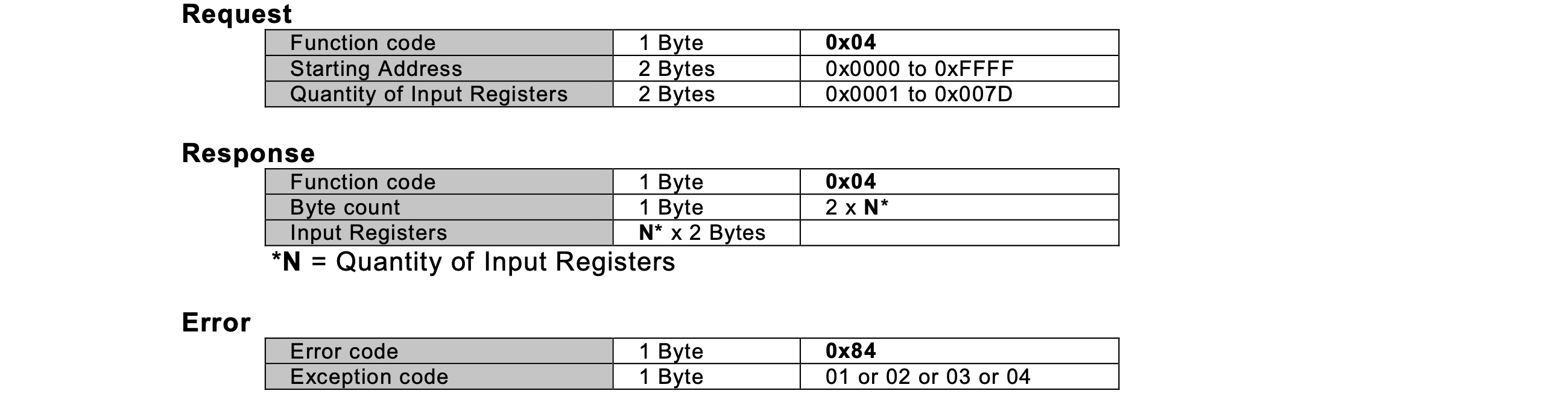
- Start address:
0x0054- Quantity of input registers:
0x000C= 12 registers
- Quantity of input registers:
- Start address:
- CRC:
B0 97
The response must contain a byte count of 0x18 followed by 24 data bytes because 12 registers were requested:
01 04 18 <24 data bytes> <CRC low> <CRC high>
Each pair of data bytes represents one 16-bit input register. The application must define how those registers map to values such as forces, moments, byte order, and scaling.